|
|
|
Who's Online
There currently are 5682 guests online. |
|
Categories
|
|
Information
|
|
Featured Product
|
|
|
 |
|
|
There are currently no product reviews.
 ;
This is a great and complete Service Manual for the Sharp GF8585HB. Giving full and detailed technical insight. Good to find these manuals online.
 ;
Everything was ok with the manual. If I have a small complaint, is that I ordered it during the weekend and I think you guys were closed. But I did receive it late Sunday. I will surely order from you again
;
Best Service! Very fast and easy to handle. Fast Download an you can come back every day to download again
;
Very good quality, no parts are missing and everthing is readable.
Thank you very much. :-)
;
This manual is all I need to check and repair my equipment. Thank you....
1-A. Preliminary/Final Checking and Alignment of Tape Path
Purpose: To make sure that the tape path is well stabilized. Symptom of Misalignment: If the tape path is unstable, the tape will be damaged. Note: Do not use an Alignment Tape for this procedure. If the unit is not correctly aligned, the tape may be damaged. 1. Playback a blank cassette tape and check to see that the tape runs without creasing at Guide Rollers [2] and [3], and at points A and B on the lead surface. (Refer to Fig. M3 and M4.) 2. If creasing is apparent, align the height of the guide rollers by turning the top of Guide Rollers [2] and [3] with a Guide Roller Adj. Screwdriver. (Refer to Fig. M3 and M5.)
Guide Roller [2] Guide Roller [3]
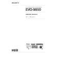
3. Check to see that the tape runs without creasing at Take-up Guide Post [4] or without snaking between Guide Roller [3] and AC Head. (Fig. M3 and M5) 4. If creasing or snaking is apparent, adjust the Tilt Adj. Screw of the AC Head. (Fig. M6)
Azimuth Adj. Screw
AC Head X-Value Adj. Screwdriver
Tilt Adj. Screw
Fig. M6
1-B. X Value Alignment
Purpose: To align the Horizontal Position of the Audio/Control/ Erase Head. Symptom of Misalignment: If the Horizontal Position of the Audio/Control/Erase Head is not properly aligned, maximum envelope cannot be obtained at the Neutral position of the Tracking Control Circuit. Fig. M3 1. Connect the oscilloscope to TP1403 (HA-MONITOR) and TP1201 (CTL) on the Main CBA. Use TP1401 (RF-SW) as a trigger. 2. Playback the Gray Scale of the Alignment Tape (FL8NW) and confirm that the PB FM signal is present. 3. Set the Tracking Control Circuit to the center position by pressing CH UP button then � PLAY � button on the unit. (Refer to note on bottom of page 2-3-4.)
ACE Head
A
B Take-up Guide Post [4]
Lead Surface of Cylinder
Tape
Fig. M4
4. Use the X-Value Adj. Screwdriver so that the PB FM signal at TP1403 (HA-MONITOR) is maximum. (Fig. M6) 5. Press CH UP button on the unit until the CTL waveform has shifted by approx. +2msec. Make sure that the envelope is simply attenuated (shrinks in height) during this process so that you will know the envelope has been at its peak.
Correct
Guide Roller Tape
Incorrect
Take-up Guide Post Tape
Fig. M5
2-3-3
TD951MA
|
|
|
> |
|