|
|
|
Who's Online
There currently are 5965 guests online. |
|
Categories
|
|
Information
|
|
Featured Product
|
|
|
 |
|
|
There are currently no product reviews.
 ;
Very fast and perfect delivery. Clear and well scanned. A lot of work professionally realized.
Again thak you a lot
 ;
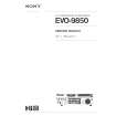
This manual is accurate and of high quality. It is only volume 2 of the service manual. This is schematic, parts lists, and exploded mechanical drawings. The theory of operation and the diss-assembly instructions are in volume 1. The unit can be tricky to dis-assemble portions of so the volume 1 manual can be important. The product description of the manual is accurate but it does not say anything about volume 1 and the image of the front page does clearly say Volume 2.
;
Wellll again thank you very much fast and effective. Clear and well done for such an old TV!!!!
;
It has all the information you will need to fix it. The main circuit diagram is only A4 but being a PDF, you can print it to any size - I did it on two sheets of A3 and it didnt lose any detail - just made it readable when pinned up above the bench. I've found the fault, just need to buy some obscure bits to get it going again!
I cant fault the process, I paid for the manual in the morning and it was ready to download by lunch time.
;
Very good copy in a 54 pages PDF archive. This is my sixth purchase here. :)
SERVICE NOTE
1. POWER SUPPLY DURING REPAIRS
In this unit, about 10 seconds after power is supplied to the battery terminal using the regulated power supply (8.4V), the power is shut off so that the unit cannot operate. These following two methods are available to prevent this. Take note of which to use during repairs. Method 1. Connect the servicing remote commander RM-95 (J-6082-053-B) to the LANC jack, and set the commander switch to the �ADJ� side. Method 2. Use the DC IN terminal. (Use the AC power adaptor. (AC-L10, AC-VQ800 etc. ))
2.
1 2 3 4 5 6
TO TAKE OUT A CASSETTE WHEN NOT EJECT (FORCE EJECT)
Refer to 2-3. to remove the upper handle block assembly. Refer to 2-5. to remove the cabinet (L) assembly. Refer to 2-5. to remove the mechanism deck (Including VC-242 board and DD-138 board). Remove DD-138 board from the mechanism deck (Including VC-242 board). Remove the CN022 (27P 0.3 mm) of VC-242 board. Supply +4.5V from the DC power supply to the loading motor and unload with a pressing the cassette compartment.
DC power supply (+4.5V)
: loading : unloading
Disconnect from CN022 (27P) of VC-242 board.
Loading motor
http://cxema.ru
�6�
|
|
|
> |
|